# Coursera: Hands-on quantum error correction with Google Quantum AI
Recently, Google Quantum team published a [breakthrough](https://blog.google/technology/research/quantum-echoes-willow-verifiable-quantum-advantage/) about the verifiable quantum advantage on hardware. Quantum error correction one of the fundamental parts in quantum computing and I skipped that part in previous learnings. After failing to understand the work by just chatting with Gemini (master of analogy but still failed to resolve my questions), I decided to pick up this Coursera class again and finish it.
- [link](https://www.coursera.org/learn/quantum-error-correction/home/welcome)
---
Takeaways:
- Errors can happen everywhere even before measurement.
- some assumptions are still guaranteed by hardwares (like only $\ket{0}$ or $\ket{1}$ state).
- different errors are decomposed to linear combination of X errors and Z errors
- parity check is the key
- Encoding:
- Use multiple physical qubits to represent one logical qubit
- stabilizers can be used to represent a state.
- The surface code is easier to understand a state than using stabilizers-repr or state-repr
- $X$ / $Z$ operator are redesigned. also $M$ and $M_X$ measurement.
- Error detection:
- surface code + time-axis consistency check forms a 3d grid. Minimum Weight Perfect Matching is used to determine the correct output.
- Correct is not applied to the qubits but fixed at the decode (software) time.
- Crumble is a tool to determine the detection region.
- Stim is a tool to simulate the stabilizer in a large scale. This can help understand how many physical qubits (distance) I need in order to reach X consistency rate given Y hardware error rate.
Comments:
- Good intro to QEC but maybe not the best place if you learn QC from scratch.
- Check the answer if you get blocked by the quiz. Some info cannot be learned from the lecture easily.
---
(Notes):
### What is QC:
- Annealers: D-wave. qubits not on coherence but on applying control on the goal; an optimizer; not scalable
- Ion traps: a sufface patterned with electrodes that trap individual atomic ion; high fedility; bottomneck: scale, speed.
- Neutral atoms: trap with lasers; large qubit counts; challenges speed; atoms leaves wells;
- photonic: generate photons on chip; probabilistically entangle them ; changlleses overcoming loss and rapid switching pohotons
- Quantum dots: inividual electrons held in electrostatic fields; chellegnes: single borken split QC into two
- supercondcting:
- Google/IBM;
- Qubit are tunable frequency reasonant circuits;
- first execite state is |1>, not moving is |0> etc
- but string might have higher frequencies (higher excite state)
- changlleges:
- higher states cannot be used
- temperature (thermel enougy needs to be smaller than create energy gap to maintain circuits states)
- circuits are bigger compared single ion/photon
- circuits dont have 100% yield (some qubits and couplers unusable)
### Quantum Stats and circuits:
- classic computer: states, bit strings, operations(and, or, xor, +)
- Quautum states:
$\ket{\Psi} = \sum_{i=0}^{2^n-1}c_i\ket{i}, c_i \in \mathbb{C}, \sum_{i=0}^{2^n-1}|c_i|^2 = 1$
- Gates:
- X gate:
- $X\ket{0} = \ket{1}$
- $X\ket{1} = \ket{0}$
- Z gate:
- $Z\ket{0} = \ket{0}$
- $Z\ket{1} = -\ket{1}$
- Quantum Circuit
- one qubit in one row
- x-axis is time
- H gate:
- $H\ket{0} = \ket{+}$
- $H\ket{1} = \ket{-}$
- CNOT gate:
- $CNOT(1, 0)\ket{00} = \ket{00}$
- $CNOT(1, 0)\ket{01} = \ket{01}$
- $CNOT(1, 0)\ket{10} = \ket{11}$
- $CNOT(1, 0)\ket{11} = \ket{10}$
- Control-Z gate:
- $CZ(1, 0)\ket{00} = \ket{00}$
- $CZ(1, 0)\ket{01} = \ket{01}$
- $CZ(1, 0)\ket{10} = \ket{10}$
- $CZ(1, 0)\ket{11} = -\ket{11}$
- Measurement Gate:
- measure one, all entangled will collapse
### QEC I:
- classical error correction fundamentals
- setup: a bit 0/1
- question: probability p per unit time of flipping
- Solution: store multiple copies periodicially take majority vote
- multiple physical bits -> one logical bit
- code distance:
- the number of bits that need to be flipped to convert logical 0 into logical 1
- majority vote: dont' actually need to measure directly
- pairwise-parity: check the pairty; use Minimum weight perfect matching (MWPM) to decode;
- quantum errors
- e.g. leakage: higher stats, spreadable
- measurement can cause leakage as well
- high-energy impacts
- assumption: even with error the states can be represent by $\ket{0}$ or $|\ket{1}$. even leakage to higher state
- gates/init is followed by an error matrix; measure follows an error matrix;
- error matrix can be express as a linear combination of X (bit flip) and Z (phase flip) errors.
### Quantum error correction II: Detecting bit-flips and phase-flips
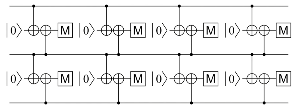
repeated detection (for bit flip):
- no error: produce 0 output
- data error: error will be consistent in the future
- measure error: odd-one-out error (not preserved)
- (two measure bits to detect three bits)
- distance-3-code, can cope with at most (d-1)/2 (i.e. 1) errors.
- with distance increase linearly, the p(at least half error) decays exponentially (errors are independent).
- we can calculate a graph where edges-value (thickness) is the propbility of having error in that transition by assuming there is an errors.
- and use Minimum weight perfect matching (wt = -ln p_edge) to locate the error bit
- superposition will collapse if circuit is not designed properly
for phase flip (Z):

- where M_x is -H-M
### Quantum error correction III: Introduction to stabilizers
- stabilizer
- are operators that leave some useful state unchanged:
- e.g. $Z\ket{0} = \ket{0}$
- e.g. $-Z\ket{1} = \ket{1}$, i.e. $-Z$ is stablizer of $\ket{1}$, $\ket{1}$ is the eigenstates of the associcated stabilizer
- e.g. $X\ket{+} = \ket{+}$
- e.g. $-X\ket{-} = \ket{-}$
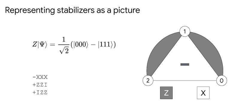
- e.g $\ket{\Psi} = \frac{1}{\sqrt{2}}(\ket{000}+\ket{111})$ is stablilized by three independent stabilizers:
- $+XXX$, $+ZZI$, $IZZ$,
- Notice that - $+XXX$, $+ZZI$, $IZZ$, $ZIZ$ is not a set of stablizer because $ZIZ=(ZZI)(IZZ)$.
- if there is an error for example $X_2$ then we will have:
- $(-Z_2Z_1)X_2\ket{\Psi} = X_2\ket{\Psi}$ or $+XXX$, $-ZZI$, $IZZ$
- If we can determine how to measure the sign of a stabilizer, we can detect errors
- General operator measure:
```
0: ───H───@───H───M('m')───
│
1: ───────A────────────────
│
2: ───────A────────────────
│
3: ───────A────────────────
```
- final result: = $ \frac{1}{\sqrt{2}} \left( |0\rangle \frac{1}{\sqrt{2}} (|\Psi\rangle + A|\Psi\rangle) + |1\rangle \frac{1}{\sqrt{2}} (|\Psi\rangle - A|\Psi\rangle) \right)$
- A zero measurement means that the output is the +1 eigenstate of A
- One means -1 eigenstate
- example
- error $X_1\ket{\Psi}$ will map stabilizers to +XXX, -ZZI, -IZZ
- error $X_0\ket{\Psi}$ will map stabilizers to +XXX, +ZZI, -IZZ
- represent it in a picture:
- ways to represent a state: explicit state (combination of all cases); set of stabilizers; picture
- 
### Some math:
- The following video confuses me and I had to chat with Gemini to figure out the underlying maths. It's essential to me to understand how the stabilizer works but unfortunately, it's not explicitly taught in the slides/videos:
- a stablilizer $S$ can detect error $E$ iff when $S$ and $E$ are **anti-commute**: $S\cdot E = -E \cdot S$
- $S(E|\psi\rangle) = (SE)|\psi\rangle = (-ES)|\psi\rangle = -E(S|\psi\rangle) = -E(+1|\psi\rangle) = \mathbf{(-1)}(E|\psi\rangle)$
- About the stabilizer :
- $S_Z$ (to measure X error):
- Use $Z \otimes Z \otimes Z ...$.
- It cares about $\ket{0}$ and $\ket{1}$. $Z\ket{0} = (+1)\ket{0}$, $Z\ket{1} = (-1)\ket{1}$.
- The final result is $(-1)^t$ where $t$ is the number bits get flipped to $\ket{1}$. it will be $-1$ if odd parity is detected.
- $S_X$ (to measure Z error):
- Use $X \otimes X \otimes X ...$ to detect.
- It cares about $\ket{+}$ and $\ket{-}$. $X\ket{+} = (+1)\ket{+}$, $X\ket{-} = (-1)\ket{-}$.
- In order to get the information from the input qubits ( $\ket{-}$ or $\ket{+}$ ), the measure bit is init to $\ket{+}$ and the magic of phase kickback:
- $CNOT(M, I)\ket{-}_I\ket{+}_M=\ket{-}_I\ket{-}_M$
- $CNOT(M, I)\ket{+}_I\ket{+}_M=\ket{+}_I\ket{+}_M$
- the information of input bit $\ket{-}$ is kicked back to make the measure bit $\ket{+}$ becomes $\ket{-}$.
- Why not apply H gate to every input and use CNOT(I, M) to aggregate the result?
- that's **Destructive Measurement** because the input is touched.
- Also, we want to apply $S_X$ and $S_Z$ on the same bit at the same time.
### Quantum error correction IV: The surface code
- surface code is more easy to understand than stabilzier-representation or explicity state-representation
- multiple physical qubits are used to represent one logical qubit
- To apply a X gate to the logical qubit (we named that $X_L$ gate), we need to operator on multiple physical bits in this way:
- Any chain of X operators from top boundary to bot that commutes with all stabilizers transforms the state identically.
- Example: 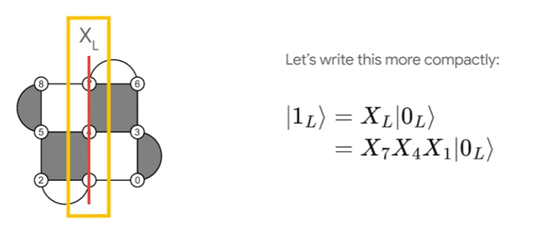
- a general way to express $X_L$ operator and $Z_L$ operator: 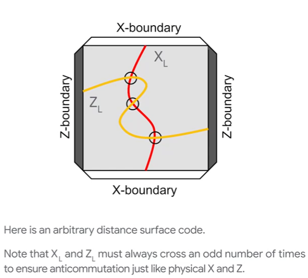
- During measurement,
- If we want to know whether $X_L$ gate is applied, we can do a Z-boundary-based measurement. Because the intersection of $X_L$ and $Z_L$ are always odd, the xor result (parity) is the answer.
- each "cube" is one stabilizer
- to prevent error to be propagated through gates and makes the errors dependent
- order of qubits in each stabilizer measurement matters
- if not indexed propertly, it's possible that when we have two errors in the stabilizer that leads to 4 data error, and therefore a logical error.
- Init and measurement
- init all and measure all qubits.
- also we have a time-axis for the measurement. and built a 3d graph and runMinimum Weight Perfect Matching.
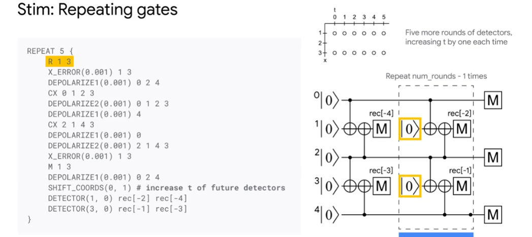
### Intro to Stim
- a fast tool to simulate stablizer
- lambda: suppression factor how fast logical error rate decreases when phsycial bits increases
- 
### Introduction to Crumble
- A tool to understand how information propagate in the surface code.
- 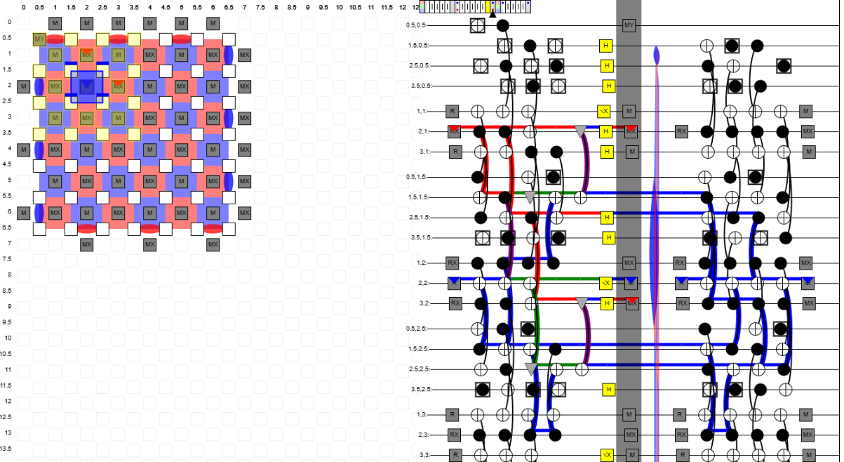
- Building detection region is tricky (select the minimal set of bits to measure) and requires exp.